Setting the Channels
Differently from other oscilloscopes, in HScope you can set the voltage input range for each channel. The concept of Volts/division is just reported as information but it is not really practical since the signal can be zoomed and shifted on the screen and measured with absolute scales and relative cursors.
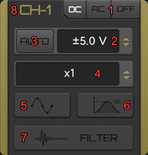
- DC/AC/OFF Button: can switch the input coupling mode to DC, AC or switch off the channel.
- Input Voltage Selector: it set the oscilloscope maximum input range.
- AUTO Button: automatically switch the input voltage according the input signal.
- Probe Selector: set the current hardware probe used by the oscilloscope on the channel.
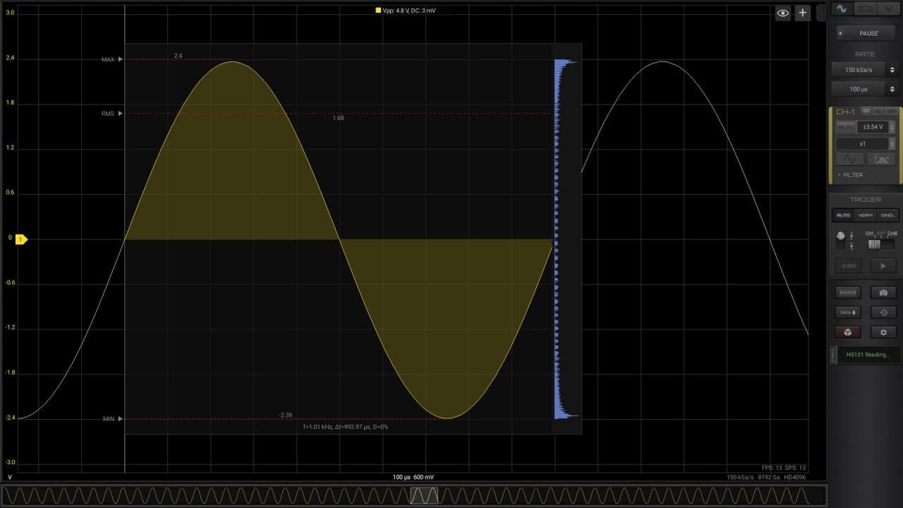
- Samples Button: by enabling it you can see the actual samples by zooming in the signal on the screen.
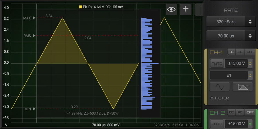
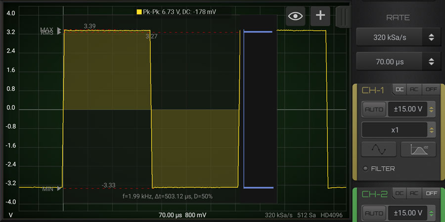
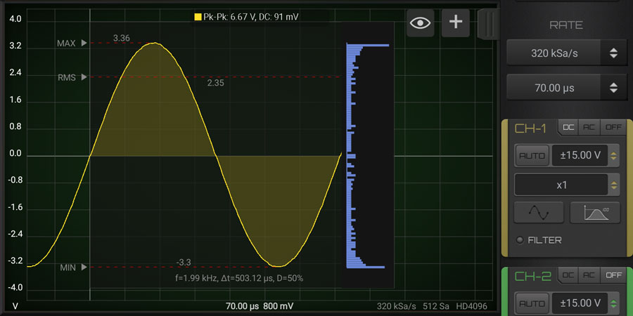
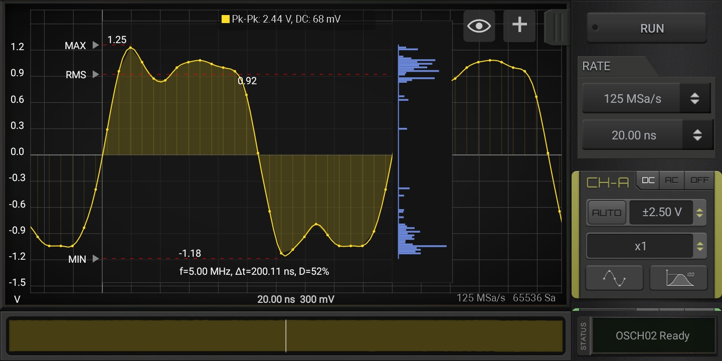
- Statistics Button: it show the main statistics for periodic signals by showing the details of 1 period of the main frequency. HScope support 2 kind of statistics, press 1 time for the simple one, press another time for the Histogram, a last time to turn them off.
- Filters: to enable filters on the channel (check the Filters section).
- Channel Name: you can change the channel name by clicking here. The new name will be shown on the report and saved in the waveform file.
1. DC/AC/OFF Button
Selecting DC the signal goes to screen AS-IS (with AC and DC components), selecting AC the signal pass into a filter (that can be hardware or software according the device) so that on screen and in computation is considered just the AC component.
2. Input Voltage Selector
This value is oscilloscope depending and change according the actual calibration. To benefit of the highest vertical resolution it is suggested to use the lowest range which include the measured signal.
3. AUTO Button
Selecting the button AUTO the software automatically set the input voltage selector according to the signal. It is intended to be use only for time invariant signals (like a sine wave) otherwise the input range will be changed very time the input signal change. This function is limited just to high voltage ranges. Lower voltage selection should still come manually.
4. Probes Selector
This setting won't affect the hardware settings but it will affect the final readings since the data will be computed according the probe settings.
IMPORTANT: Probe setting MUST reflect the probe hardware to avoid damage to the device or wrong readings. (ie: you can set x10 in HScope only if the hardware probe has x10 switch selected)
In case you need to measure stronger signals the Probe should have a switch that allow to attenuate the input signal. If you change the switch of your probe to the position x10, the input signal will be attenuated by a factor 10. This means that using the Oscilloscope range ±5V with a probe x10 you can see signals up to ±50V (50V / 10 = 5V). In visualization the App already calculate this scaling factor, so if you use a probe x10 just select in the Channel configurations the factor x10 and play with the voltage ranges (it will show you the possible range you can select).
On the market are available different kind of probes (also associated to different units like Ampere,...). You can add or download new probes in the Settings → Probes panel.
VOLTAGE RANGES (SAMPLE)
- Native Hardware Input Ranges
(with Probe x1) ±0.5V, ±1V, ±2.5V, ±5V - Input Ranges after using Probe
(with Probe x10) ±5V, ±10V, ±25V, ±50V
6. Statistics
- First press: full statistics
- Second press: histogram
- Third press: statistics off